Concept
A cloud chamber is a confined space in which vapors, typically of some alcohol such as isopropanol, are very dense. When charged particles pass through the vapors, they ionize the surrounding molecules, and the vapors condense into a fog trail around the path they travel. This is not unlike white trails created by airplanes in the sky.
A more detailed explanation on wikipedia: Cloud chamber.
The cloud chamber I built and show here is based on a temperature gradiant between the bottom and the top of the chamber. The top of the chamber is at room temperature or slightly more, while the bottom is cooled to about -30°C with the help of Peltier modules. A supply of isopropyl alcohol is placed at the top of the chamber, and evaporates. The alcohol vapors being heavier than air, they fall down to the cold part of the chamber, and thus cool down. As cold air can "hold" less vapors, a saturated layer of alcohol formsin the lower part of the chamber.
Construction
As mentioned above, the setup relies on a low temperature at the bottom of the chamber. The base of the chamber will be a metal plate (at the beginning on the photos, copper, but it will become an aluminum plate in the final version for a greater contrast), that should be cooled down. The cooling is done here by the Peltier effect, that is, by modules (in white in figure 1)) which, by applying a voltage, of about 12V here, produce a temperature difference between their two faces, which can be up to 60°C in good conditions.
Of course, the peltier modules are oriented so that the upper part is the cold side, and will be glued (with thermal paste) to the base of the fog chamber. The lower, and thus hot part, of the peltier must be cooled. Indeed, each peltier will be powered by about 60W, and leaving the hot side open to the air is not enough to dissipate all the heat. Since the temperature difference between the hot and cold parts of the peltiers is more or less fixed (say 60°C), keeping the hot part at +30°C gives a cold part at -30°C. If the hot part of the peltier is not actively cooled, it could rise to very high temperatures (more than 100°C).
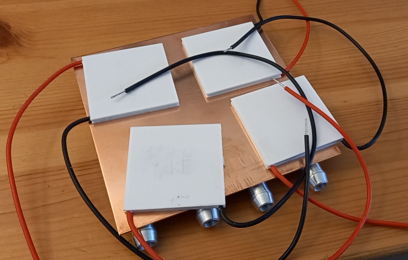
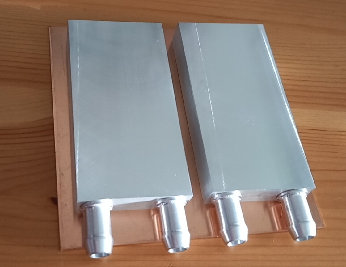
The peltier modules are here cooled by a typical liquid cooling system, which can be found for instance in some computers. On figure 1 we can see the first element of the cooling system: two aluminium heat exchangers, which we can see better in figure 2. A liquid will flow in the exchangers to capture the heat from the peltiers, and then the liquid will be sent further into a radiator so as to dissipate its heat.
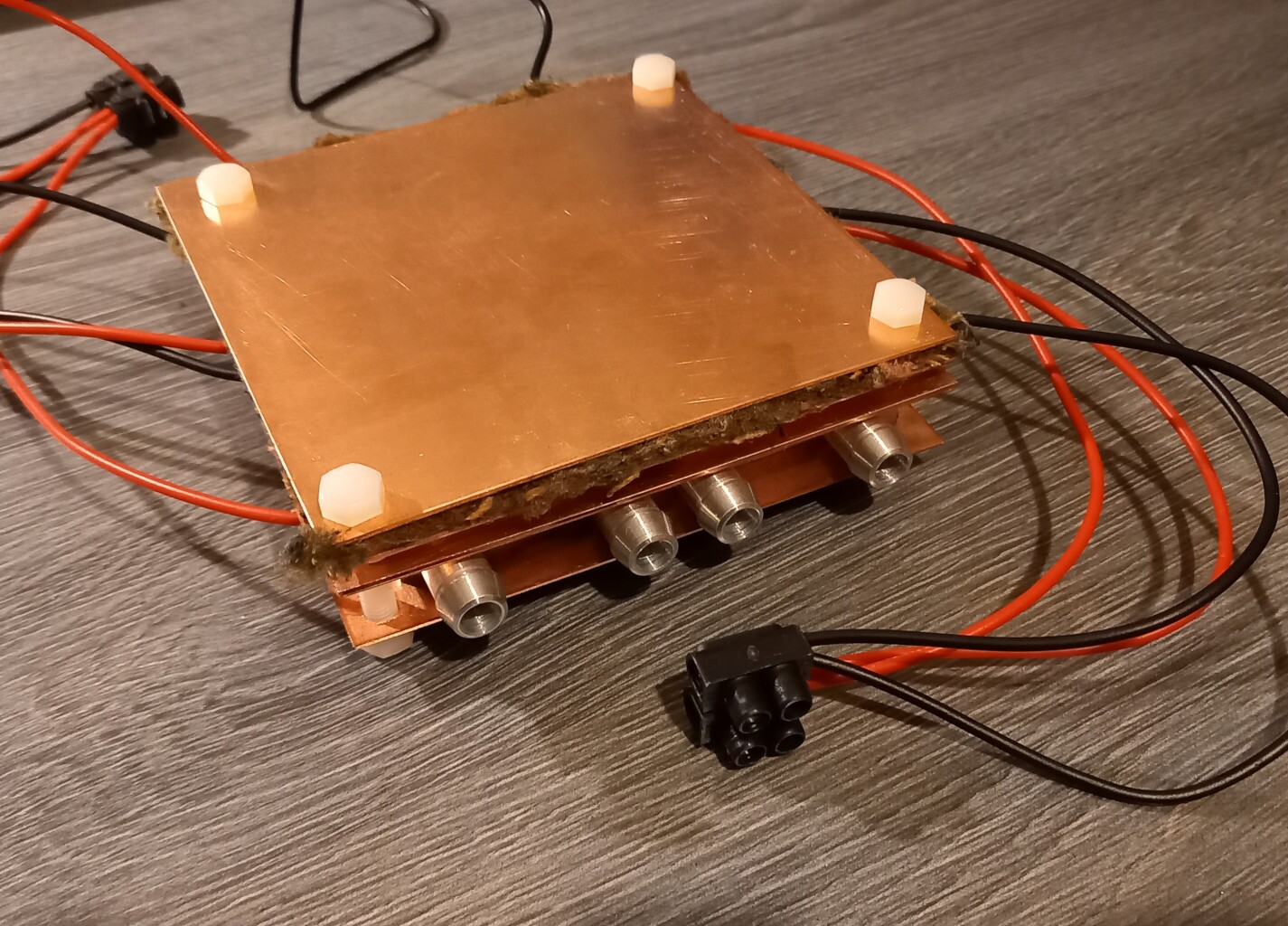
To slightly improve the temperature difference between the base of the chamber and the water cooling system, I used two layers of peltier, as can be seen in Figure 3. For efficiency reasons, the 4 peltiers on the bottom run on 12V each while the top 4 peltiers run on 3V each.
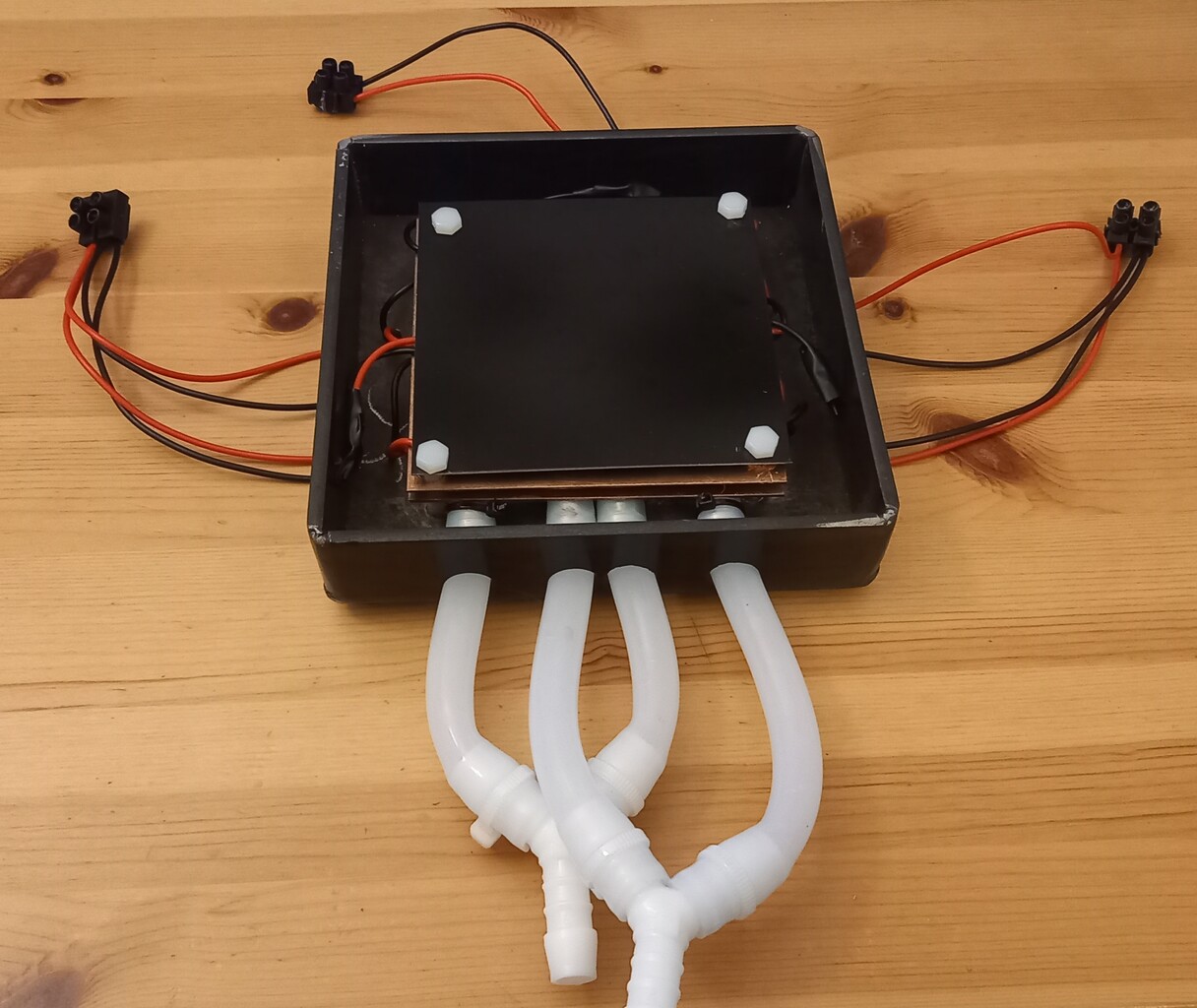
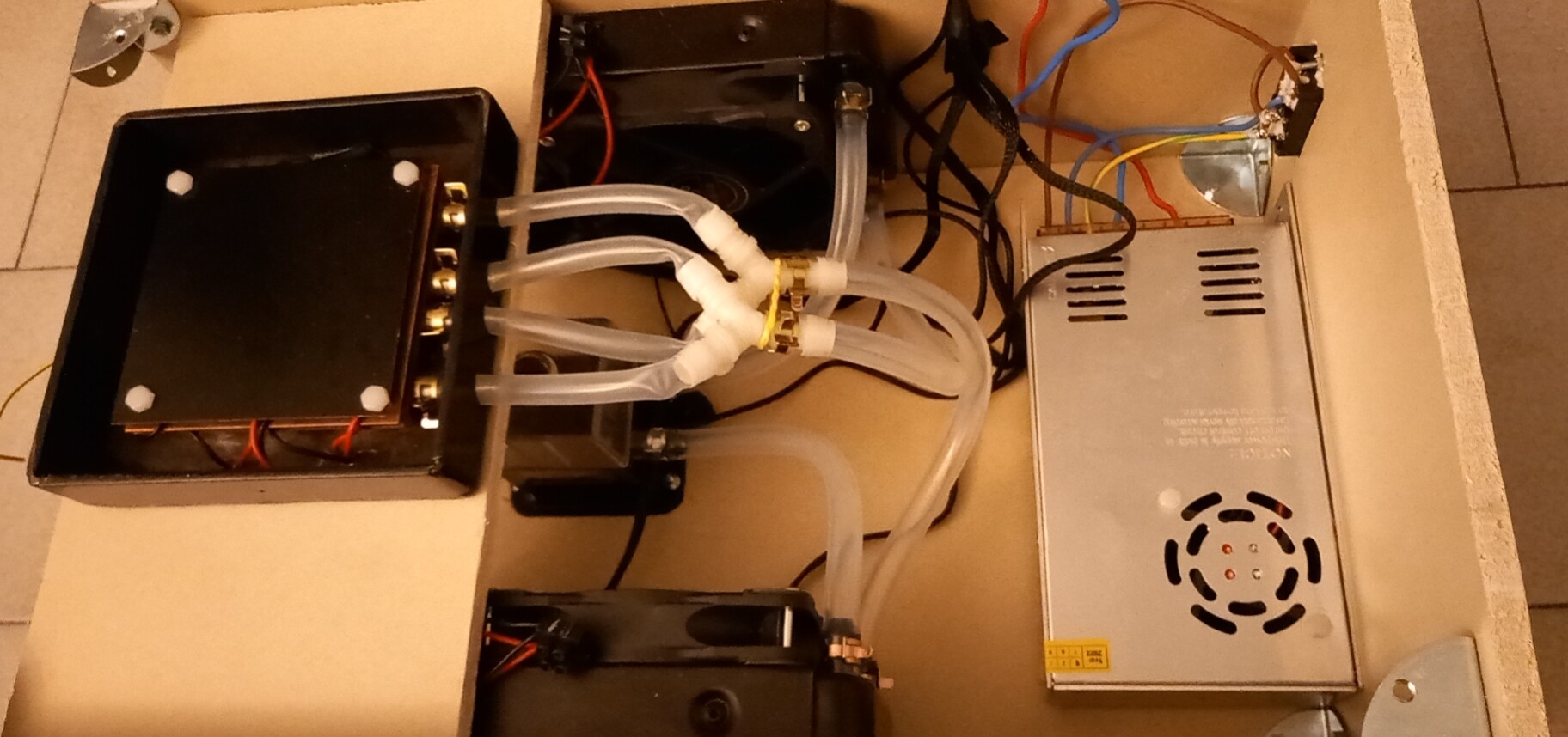
It is more convenient when everything is placed in a box, and that is what is done in picture 4. Pipes and Y-joints allow the water exchangers to run in parallel.
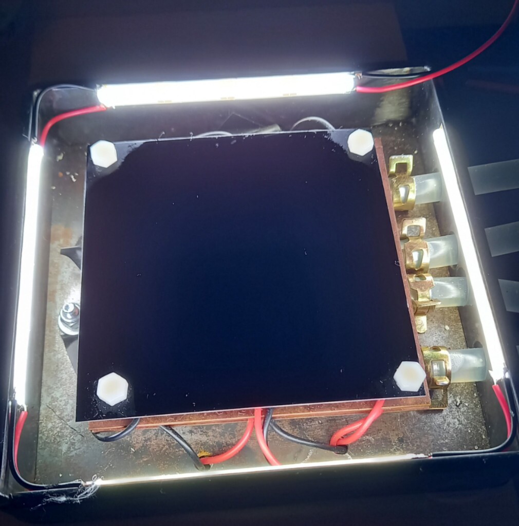
Since we want to see a fine mist appearing in the box, it is better to have a good contrast to see it. That is why the base of the box is a black anodized aluminum plate (in the final version), and that is also why I added LED light strips around the box, which can be seen in figure 5. The light will illuminate the fog in white, which can then be seen clearly on the black background.
If the "heart" of the cooling device is now more or less finished, there is still a big part: the liquid cooling system. This system takes up a lot of space, so it is convenient to make a big box to contain everything, as shown on picture 6.
The liquid cooling system is quite classical. That is to say, it contains a heat exchanger that will transfer the heat from the system that we want to cool (the peltiers) to the cooling liquid. Two radiators, each equipped with two 12x12cm fans, through which the liquid passes, allow the heat of the cooling liquid to be dissipated to the ambient air. Finally, the coolant circulates in this loop thanks to a 12V pump. Every component of this cooling loop here is made of aluminum or plastic tubes.
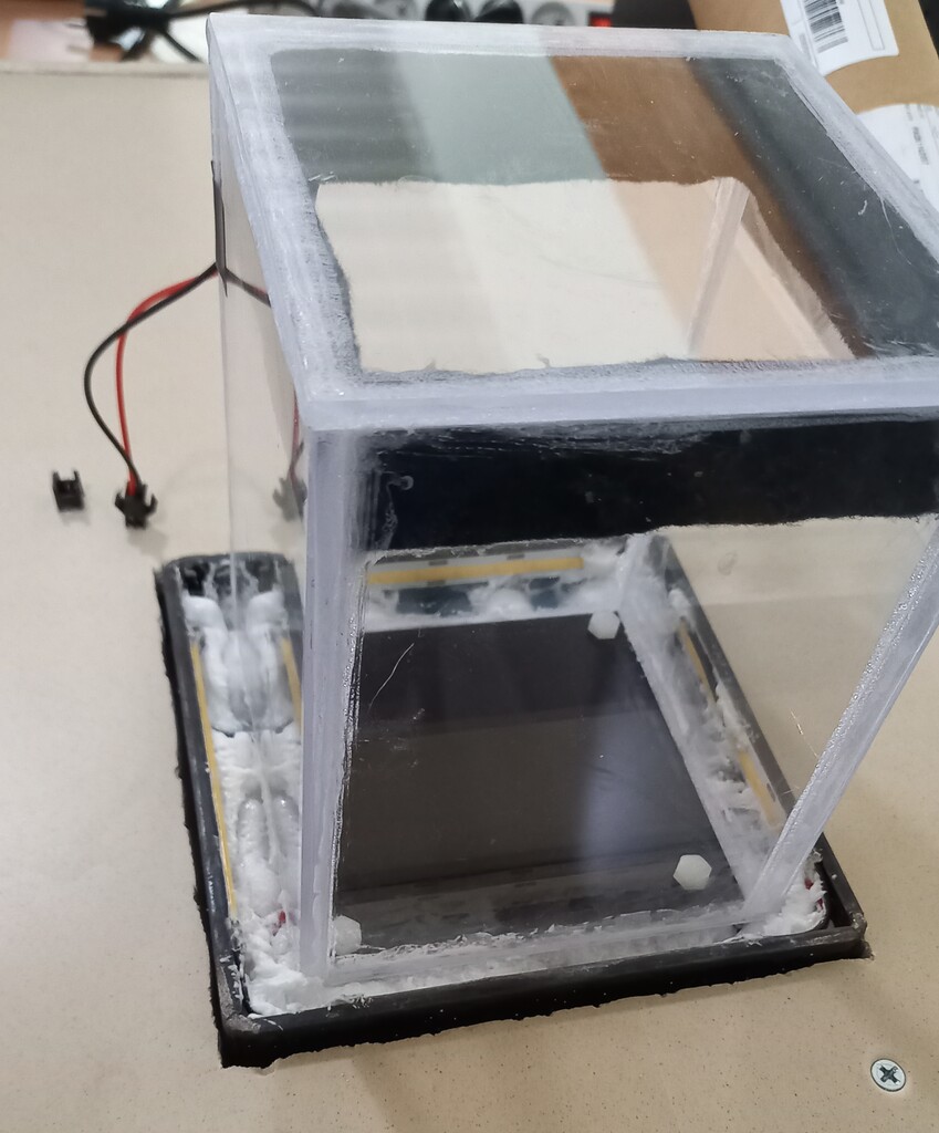
Finally, we must make the box of the actual cloud chamber. The base already exists, it is the black aluminium plate, but we have to make the 5 other sides of the box. This box has to be transparent, and for the moment I made it in polystyrene (not expanded!). You can see it on figure 7. It is possible to remove the box to access the metal plate at the bottom. Felt is glued inside the top of the box as a reservoir for isopropanol. Resistive wire runs through the felt to heat it, and thus evaporate the isopropanol. There is twice 1 meter of 60Ω/m wire running in parallel, which emit about 5W of heat in total when connected to 12V. The space in the iron box is filled with insulation, polyurethane foam.
Polystyrene is not a good choice for the box, as this plastic scratches very easily. Also, the isopropanol tends to attack the plastic glue. I will make a glass box soon.
Results
The cloud chamber is easily operated. First, one has to soak the felts in the polystyrene box with isopropanol, then pour a little bit of isopropanol on the black metal plate. Spreading isopropanol on the vertical walls of the chamber seems to help get more vapors. Next, place a radioactive source on the metal plate, put the transparent box on its base, and plug the machine in an outlet.
Results on the video Figure 8
As indicated in the description of the video, I use welding rods doped with thorium dioxide. Thorium is radioactive and decays by emitting α (alpha) particles, which are in fact helium nuclei. These nuclei are devoid of electrons and therefore have a charge of +2e. The passage of charged particles in the fog ionizes some particles which makes fog condenses at the place where the particle passes, creating the white traces that we see. Gamma rays are also emitted, but they are not charged (they are photons), and are therefore invisible in the chamber.
The difference in lengths of each traces are due to the direction of emission of the particles, which is perfectly random. Indeed, the alcohol vapors are sufficiently concentrated to form a fog only on a layer of approximately 1cm thickness in the bottom of the box. If a particle is emitted towards the base or towards the top of the box, it will be almost invisible, as the trace will be very short. To see a long trace, a particle must be emitted horizontally. The small traces seen in the video of figure 8 are thus particles emitted upwards or downwards, and which remain only a very little time in the 1cm thick layer.
The activity (the number of radioactive decays per second) of the rods is low, hence the few visible traces. On the other hand, the low activity of the rods makes them not (too) dangerous. Moreover, these α particles of which we see the traces are not dangerous outside the body, as they are stopped by a simple sheet of paper, and thus easily by the skin.
Useful links
Very good website (mostly in english) about cloud chambers: www.cloudylabs.fr. I should have visited it before, there are a lot of advices on how to make cloud chambers, how they work, and some very nice videos.